
OEM Manufacturer China 55crsia 60si2mn Oil Tempered Spring Steel Wire
We stick to our enterprise spirit of “Quality, Efficiency, Innovation and Integrity”. We aim to create more value for our customers with our rich resources, advanced machinery, experienced workers and excellent services for OEM Manufacturer China 55crsia 60si2mn Oil Tempered Spring Steel Wire, Be sure to never wait to get in touch with us for anyone who is interested within our solutions. We firmly believe that our products and solutions will make you happy.
We stick to our enterprise spirit of “Quality, Efficiency, Innovation and Integrity”. We aim to create more value for our customers with our rich resources, advanced machinery, experienced workers and excellent services for China Spring Steel Wire, Wire, We have been seeking the chances to meet all the friends from both at home and abroad for the win-win cooperation. We sincerely hope to have long-term cooperation with all of you on the bases of mutual benefit and common development.
Details
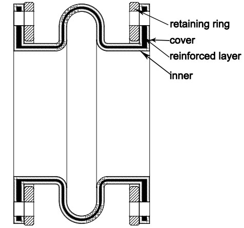
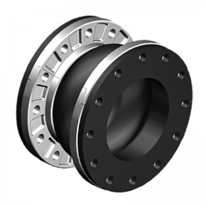
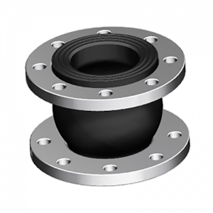
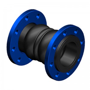
The spool type rubber joint is molded type, with a metal collar reinforced at the neck of the body. The ST stype uses a light reaining ring to support the integral flange. STF is filled arch, with 50% of the ST allowed movements, but it has 4 times spring rates than hollow arch.
| Specifications | I | II | III |
| Working Pressure Mpa (Kgf/Cm2) | 1Mpa (10) | 1.6 (16) | 2.5 (25) |
| Test Pressure | 1.5Mpa | 2.4Mpa | 3.75Mpa |
| Burst Pressure Mpa (Kgf/Cm2) | 3 (30) | 4.8 (48) | 5.5 (55) |
| Vacuum Kpa (Kgf/Cm2) | 53 (400) | 86(660) | 100 (750) |
| Materials | EPDM/NBR/SBR/NR | ||
| Diameter Range | DN15-DN600 (1/2″-24″) | ||
| Connection Method | FLANGETHREADCLAMP | ||
| Flanges Dimensions | DIN, EN,ANSI, BS, JIS and other standards | ||
| Applicable Medium | Air, compressed air, water, seawater, hot water, oil, acid, alkali etc. | ||
| Loading Port: | Qingdao, China | ||
| Shipment Terms: | FOB, CFR, CIF | ||
| Production Capacity: | 50000 set | ||
| Payment Terms: | L/C, T/T, D/P | ||
| Connection: | Flange, Thread | ||
| Flange Material: | Carbon Steel, Stainless Steel | ||
| Period of Delivery | about 21 working days | ||
|
SPOOL TYPE (ST) -American Standard ST |
||||||||||
|
Dimensions |
Movement Distance |
Operating Condition |
||||||||
|
Pipe Size |
O’all Length |
Flange OD |
Retaining Ring Thickness |
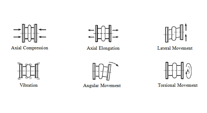
Axial Compression |
Axial Extension |
Lateral Deflection |
Angular Deflection |
Max w.p. (psi)-3,-4 |
Max Vacuum (in. of Hg)-5 |
|
|
Inch |
mm |
Inch |
Inch |
Inch |
Inch |
Inch |
Inch |
|||
|
2″ |
50 |
6″ |
6″ |
3/8″ |
7/16″ |
1/4″ |
±1/2″ |
19° |
150 |
26 |
|
2 1/2″ |
65 |
6″ |
7″ |
3/8″ |
7/16″ |
1/4″ |
±1/2″ |
15° |
150 |
26 |
|
3″ |
80 |
6″ |
7 1/2″ |
3/8″ |
7/16″ |
1/4″ |
±1/2″ |
13° |
150 |
26 |
|
4″ |
100 |
6″ |
9″ |
3/8″ |
7/16″ |
1/4″ |
±1/2″ |
10° |
150 |
26 |
|
5″ |
125 |
6″ |
10″ |
3/8″ |
7/16″ |
1/4″ |
±1/2″ |
8° |
150 |
26 |
|
6″ |
150 |
6″ |
11″ |
3/8″ |
7/16″ |
1/4″ |
±1/2″ |
6° |
150 |
26 |
|
8″ |
200 |
6″ |
13 1/2″ |
3/8″ |
11/16″ |
3/8″ |
±1/2″ |
6° |
150 |
26 |
|
10″ |
250 |
8″ |
16″ |
3/8″ |
11/16″ |
3/8″ |
±1/2″ |
5° |
150 |
26 |
|
12″ |
300 |
8″ |
19″ |
3/8″ |
11/16″ |
3/8″ |
±1/2″ |
5° |
150 |
26 |
|
14″ |
350 |
8″ |
21″ |
3/8″ |
11/16″ |
3/8″ |
±1/2″ |
4° |
150 |
15 |
|
16″ |
400 |
8″ |
23 1/2″ |
3/8″ |
11/16″ |
3/8″ |
±1/2″ |
4° |
150 |
15 |
|
18″ |
450 |
8″ |
25″ |
3/8″ |
11/16″ |
3/8″ |
±1/2″ |
3° |
150 |
15 |
|
20″ |
500 |
8″ |
27 1/2″ |
3/8″ |
13/16″ |
7/16″ |
±1/2″ |
3° |
150 |
15 |
|
24″ |
600 |
10″ |
32″ |
3/8″ |
13/16″ |
7/16″ |
±1/2″ |
3° |
150 |
15 |
|
SPOOL TYPE: FILLED ARCH (STF) -American Standard STF |
||||||||||
|
Dimensions |
Movement Distance |
Operating Condition |
||||||||
|
Pipe Size |
O’all Length |
Flange OD |
Retaining Ring Thickness |
Axial Compression |
Axial Extension |
Lateral Deflection |
Angular Deflection |
Max w.p. (psi)-3,-4 |
Max Vacuum (in. of Hg)-5 |
|
|
Inch |
mm |
Inch |
Inch |
Inch |
Inch |
Inch |
Inch |
|||
|
2″ |
50 |
6″ |
6″ |
3/8″ |
7/32″ |
1/8″ |
±1/4″ |
9.5° |
150 |
26 |
|
2 1/2″ |
65 |
6″ |
7″ |
3/8″ |
7/32″ |
1/8″ |
±1/4″ |
7.5° |
150 |
26 |
|
3″ |
80 |
6″ |
7 1/2″ |
3/8″ |
7/32″ |
1/8″ |
±1/4″ |
6.5° |
150 |
26 |
|
4″ |
100 |
6″ |
9″ |
3/8″ |
7/32″ |
1/8″ |
±1/4″ |
5° |
150 |
26 |
|
5″ |
125 |
6″ |
10″ |
3/8″ |
7/32″ |
1/8″ |
±1/4″ |
4° |
150 |
26 |
|
6″ |
150 |
6″ |
11″ |
3/8″ |
7/32″ |
1/8″ |
±1/4″ |
3° |
150 |
26 |
|
8″ |
200 |
6″ |
13 1/2″ |
3/8″ |
11/32″ |
3/16″ |
±1/4″ |
3° |
150 |
26 |
|
10″ |
250 |
8″ |
16″ |
3/8″ |
11/32″ |
3/16″ |
±1/4″ |
2.5° |
150 |
26 |
|
12″ |
300 |
8″ |
19″ |
3/8″ |
11/32″ |
3/16″ |
±1/4″ |
2.5° |
150 |
26 |
|
14″ |
350 |
8″ |
21″ |
3/8″ |
11/32″ |
3/16″ |
±1/4″ |
2° |
150 |
15 |
|
16″ |
400 |
8″ |
23 1/2″ |
3/8″ |
11/32″ |
3/16″ |
±1/4″ |
2° |
150 |
15 |
|
18″ |
450 |
8″ |
25″ |
3/8″ |
11/32″ |
3/16″ |
±1/4″ |
1.5° |
150 |
15 |
|
20″ |
500 |
8″ |
27 1/2″ |
3/8″ |
13/32″ |
7/32″ |
±1/4″ |
1.5° |
150 |
15 |
|
24″ |
600 |
10″ |
32″ |
3/8″ |
13/32″ |
7/32″ |
±1/4″ |
1.5° |
150 |
15 |
Products categories

-

Phone
-

E-mail
-

Whatsapp
whatsapp

-

WeChat
Jessy Lin

-
WeChat
Ellen Zhang


